week6
Controlling big switches
Jeff's in-class
example with a relay and a transister and a DC motor and a solenoid and electroluminescent
(EL) lighting wires.
|
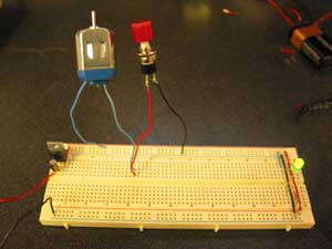
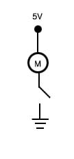
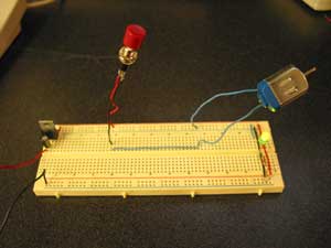
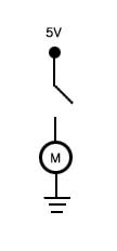
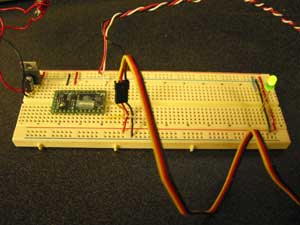
Reading and understanding diagrams of curcuit is hard for me. I was not good at physics and especailly at the part of electricity in my high school days. While working the assingnment, I got confused to read the diagram and asked to Jeff how to connect a momentary switch in series and how to make separate curcuit on the breadboard. Jeff taught the basic 5V closed circuit. Below pictures were the eample of the study. There are two ways to connect the momentary switch in series. One is connecting switch after motor and before ground (upper picture) and another is connecting it before motor after ground. Then, I could understand clearly the concept how to share the ground. Thanks, Jeff! These are the examples of simple basic curcuits and diagrams.
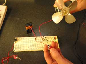
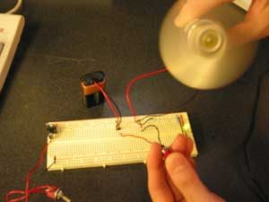
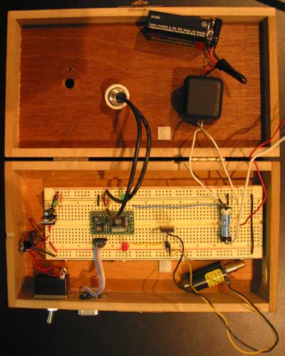
After then, I tried to solve the step #1 question. I needed to connect the DC motor to the 5V circuit and make the motor run (see the pictures above ). Then I started to use 9V DC motor. At first, I made it turn with 9V power without BX code. Although the 9V motor run, now I think, it was not good and even harmful to connect it to the breadboard which is hooked up with 5V power and 7805 voltage regulator like this. Now seeing these picture, I can remember that I could smell burning from my 7805. Making the motor run with 9V power and without transister or relay would be the reason why it became hot.
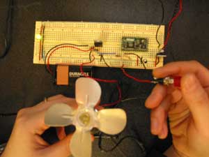
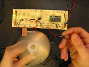
And then I tried to make the 9V DC motor turn with BX code. Because only 5V power should get into the BX 24, I had to use trasistor, which was TIP120.
Then I tested servomotor, because I had an project idea using servo motor. I'd like to know how it works. To make it run, I changed the code in the Tom Igoe's site for the servo motor on the web a little bit. I connected it with potentiometer. Here is the code which I used.
Here
are other servo motor code examples
which I reffered to.
|